In this section:
Wear and plastic flow
Wear occurs whenever a wheel rolls over a rail and transmits a tangential force. Wear rates are low unless sliding between wheel and rail and/or tangential forces are consistently high. In practice the highest wear rates occur where slip is greatest, in particular when the wheel flange contacts the gauge face. In straight track a rail crown wear rate of 0.05-0.1mm per 10MGT of traffic would not be unusual, whereas wear rates in curves could be an order of magnitude greater than this and gauge face wear rates higher again (in the absence of lubrication).
Plastic flow is bodily deformation, without loss of material, that results from high loading normal and tangential to the wheel/rail contact. Both wear and plastic flow change the shape of a rail.
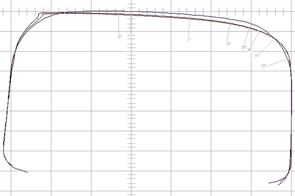
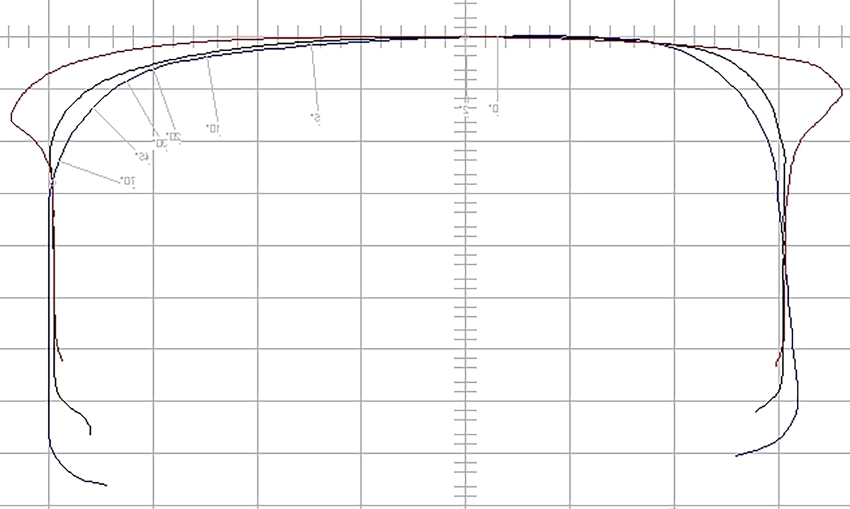
In straight track the crown of the rail wears to become slightly “flat”, conforming to the shape of the wheels that run over it. Some plastic flow occurs towards the gauge and field corners. The measurement shows a rail that has rolled a little to field, so contact is not along the centre of the rail crown and there is more wear of the gauge shoulder.
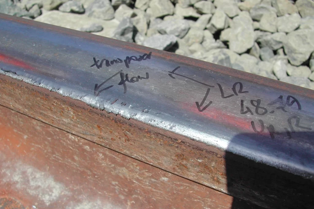
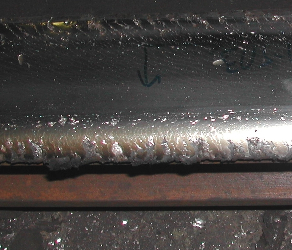
The photograph shows a case of abnormally rapid wear and plastic flow. This occurred in only a few days because the rail was transposed i.e. turned, so that the field side of the rail became the gauge. Contact stresses on the gauge corner were extremely high and flow occurred quickly to change the rail shape and reduce stresses to those that could be carried.
In curves that are sufficiently severe for there to be flange contact, the high rail usually wears until it conforms almost exactly to the corresponding flange root area on the wheel. Wear of the gauge face is known as side cutting.
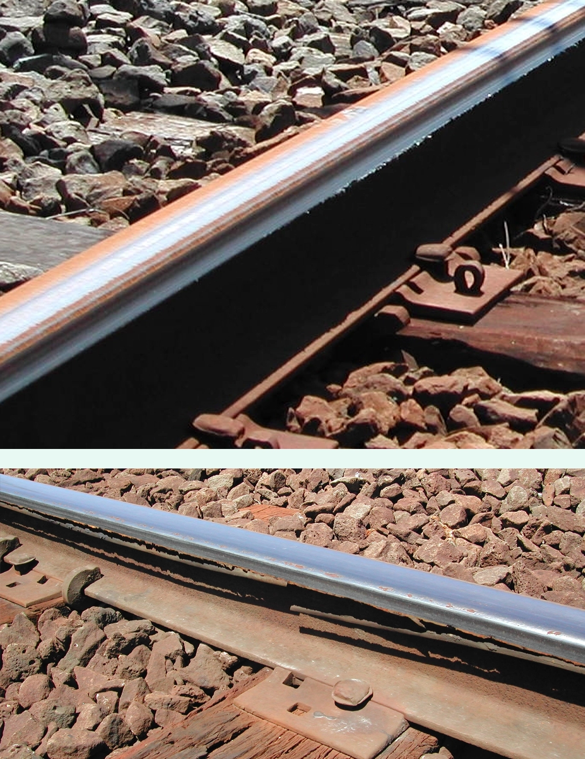
If friction is sufficiently high, the tangential force can pull material down the gauge face of the high rail, causing a lip of plastically flowed material that is detached by wheels. These slivers of material can then be seen lying alongside the rail.
Wear and deformation are best controlled with adequate lubrication, which can be applied to either the rail or the wheel.
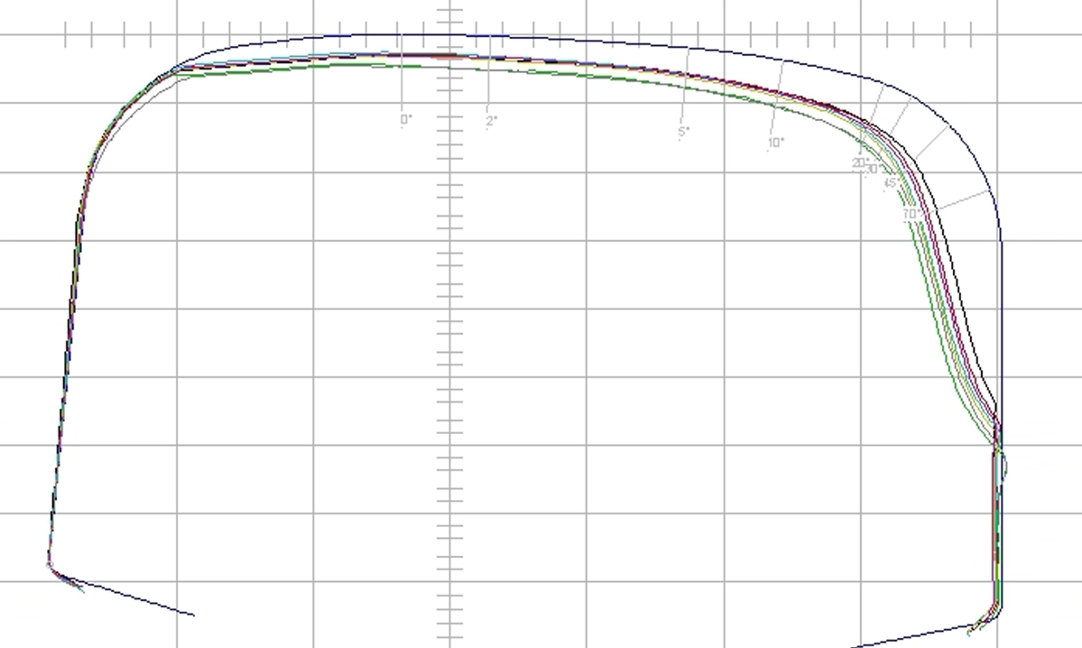
The low rail tends to be flattened as a result of wear and plastic flow. Gauge and field corners can be quite abrupt as a result of the flowed material. In extreme cases, plastic flow gives rise to flaking of the low rail with clear signs of detached material. This usually occurs only where friction is consistently high e.g. in tunnels and very dry, unlubricated areas. The loss of plastically flowed material (as in the photo) would be reflected in a high wear rate. The measurement of a low rail shows an early stage of the condition known as collapsed head. This occurs more readily in curves because tangential loads are higher.
High rail
Low rail
Rolling contact fatigue
Fatigue describes damage that occurs as a result of the incremental growth of a crack or series of cracks. Rolling contact fatigue (RCF) describes the process in which cracks grow as a result of the contact stresses between a rolling wheel and the rail. Both normal and tangential stresses are required in order for RCF to develop.
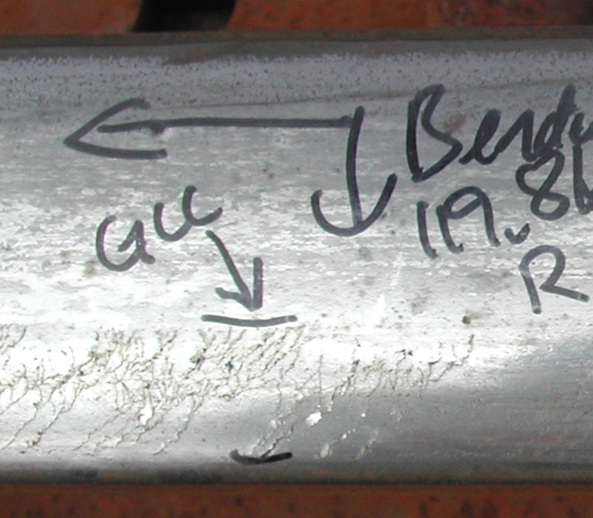
RCF that is continuous or quasi-continuous is often found along the gauge corner or gauge shoulder of the high rail. This type of RCF is known as head checking or gauge corner cracking (GCC).
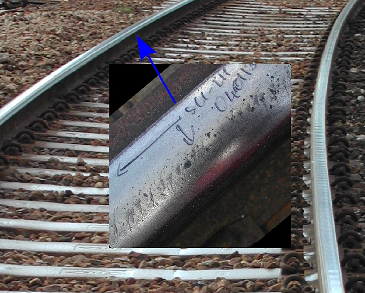
GCC is initiated by high tangential forces required for curving. The angle of the crack mouth on the rail indicates the angle of the force that initiated the crack: in the photograph above, the train would be moving towards the viewer. The force on the high rail would be backwards and towards the inside of the curve. Cracks start at the rail surface and develop into the rail at an angle of about 20° to the running surface.
Typically there are many closely-spaced cracks, only a few millimetres apart along the rail as shown below.
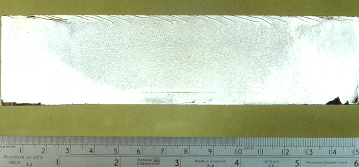
Development of GCC beyond the first few millimetres into the rail requires the presence of a liquid, in particular water. If the crack is oriented so that water can be trapped within it, this gives extremely high pressures and stress at the tip of the crack (a mechanism known as “hydraulic entrapment”). This mechanism drives the crack down through the layer of compressive residual stress near the running surface. At the edge of this layer, the crack tends to turn. If it turns down into the rail, it develops subsequently under bending and other bulk stresses. Such cracks can break a rail. Since there are usually many cracks at a similar stage of development, there may be multiple breaks. There is a great danger of derailment in such circumstances.
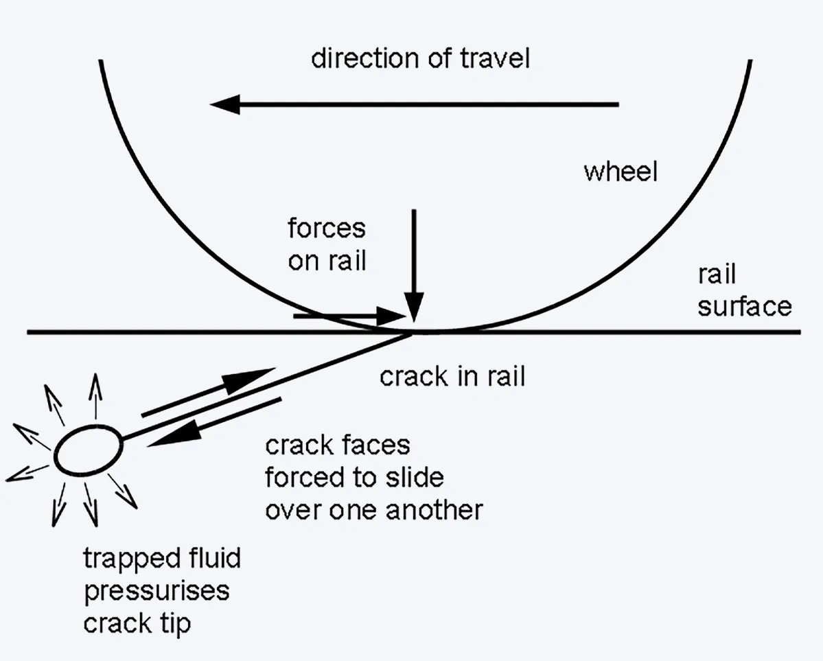
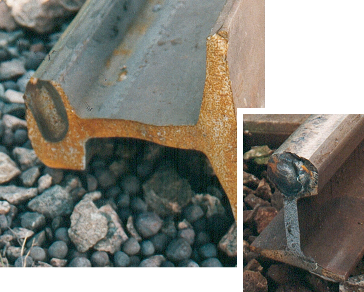
If the crack “turns” along the rail, it joins up with other cracks and a small piece of metal falls out. This is known as spalling. If fluid is not present or if the crack is oriented so that water is expelled from it, GCC does not develop beyond the first few millimetres into a rail. This is the case in dry tunnels, where GCC may look severe, but is only superficial.
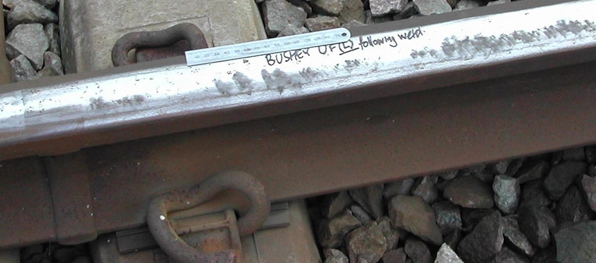
GCC initiates only occasionally on the low rail because tangential loads are usually low; and contact stresses are also lower because of the more conformal contact conditions. An example is shown of GCC on the low rail that has developed because of incomplete reprofiling around a weld in an area where trains are under high traction.
Quasi-continuous RCF occasionally occurs in straight track. If so, it is often the result of high locomotive traction, poor transverse profile or tight gauge, which forces the wheels to run along the gauge corner giving high contact stresses. RCF may occur on one rail if there is cant in straight track, since bogies then steer towards one rail.
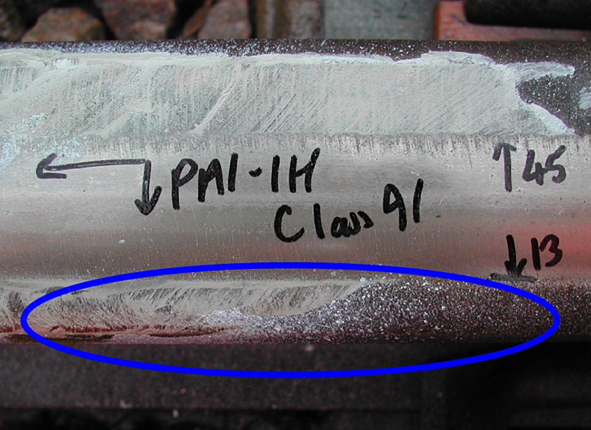
A successful and widely accepted treatment of quasi-continuous RCF is routinely to reprofile rails to establish a transverse profile that unloads critical areas of the rail (in particular the gauge shoulder) and also removes short cracks before they propagate into the rail. It is not necessary to remove cracks if the rail is profiled in such a way that cracks are no longer touched, since hydraulic entrapment can no longer operate to propagate the cracks.
RCF develops less quickly in harder rails provided these are profiled satisfactorily and this profile is maintained. There is also less plastic flow and wear on hard rails, so the profile changes more slowly than on a softer rail, and less maintenance is required in the long term. If the profile is inappropriate, RCF can develop more quickly because of the sustained high contact stresses.
Thermal damage
Although there is always some heat dissipated at the wheel/rail contact, this is rarely sufficient to cause a change in the microstructure or internal stresses in a rail. Such changes do, however, occur when wheels slip sufficiently.
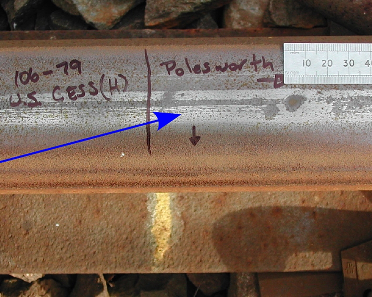
On rails that have been in service for a sufficiently long time, there is often one band or more of so-called “white phase” or “white etching layer” (WEL). These bands of WEL are extremely shallow (about 0.050mm deep) and comprise martensitic material that has resulted from many small wheelslip events, each of which is sufficient to heat the rail locally to the austenitizing temperature. The rapid quenching that arises from the rail’s high thermal inertia causes the transformation to martensite.
There are many cracks in the layer of WEL itself, but these cause the layer to detach; they do not propagate into the rail. The detached particles of WEL are essentially wear debris.
There is evidence that WEL has become less common with AC traction, probably as a result of better intrinsic wheelslip control.