With the principal exception of thermal damage, most forms of surface damage of rails are caused by normal and tangential stresses at the wheel/rail contact. These stresses result from loading on the rails, which in turn result from the way that a vehicle behaves on the track. Most damage is worse in curves, where tangential loads tend to be higher than in straight track, because these are required in order to steer the bogie (and vehicle) through the curve. Different types of damage tend to occur on high and low rails because of both the different forces acting on them and the different contact conditions.
To give a holistic understanding of some fundamental reasons for surface damage and why particular treatments work, this section contains the following:
- Calculations of the tangential forces resulting from a combination of curving and applied traction.
- A description of so-called “shakedown”, which provides a relatively simple method of determining whether a wheel or rail can carry applied loads.
Wheel/rail contact forces: effects of curving and applied traction
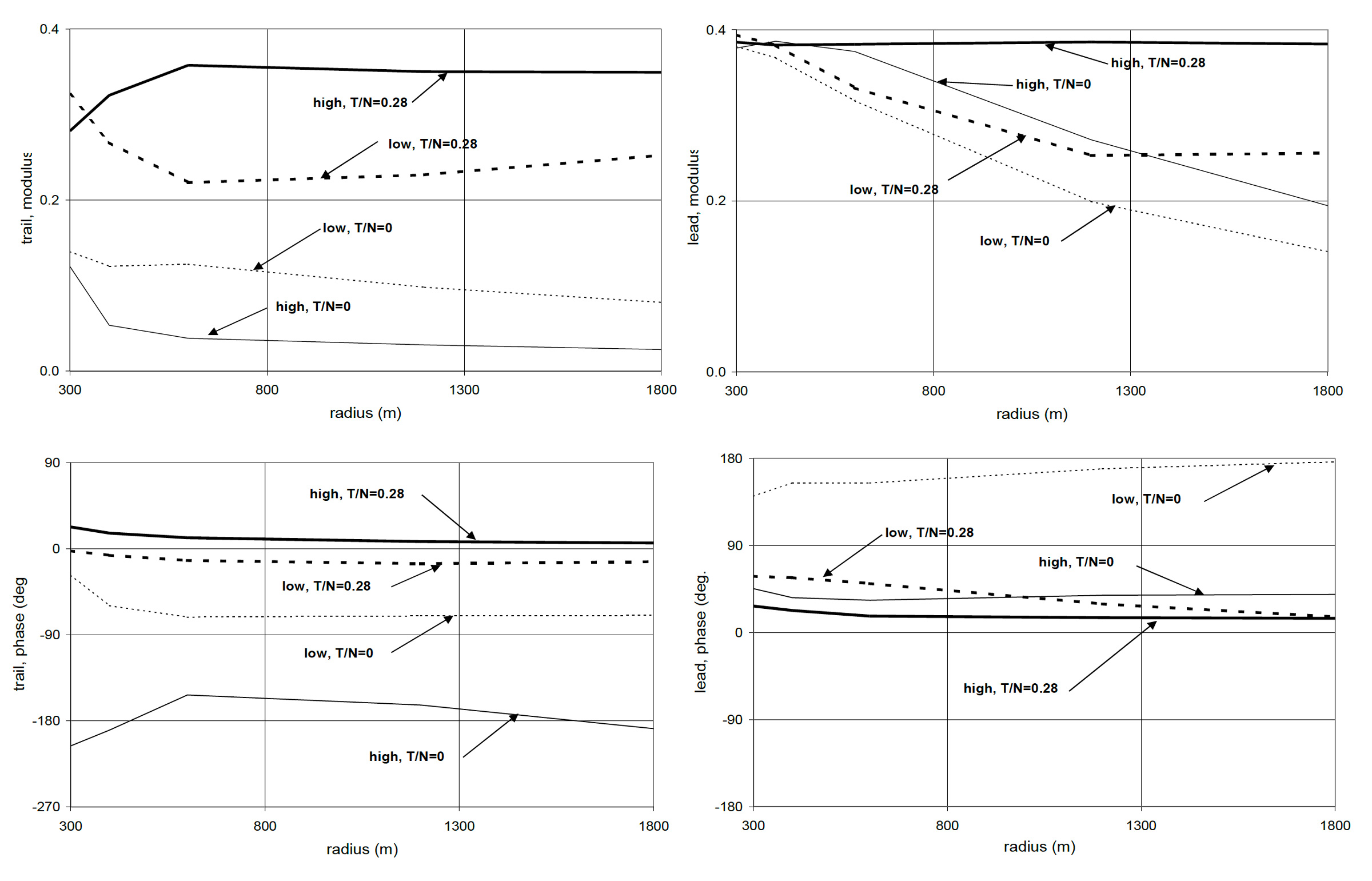
The greatest influences on tangential force are curve radius, applied traction, bogie design and applied cant. The effects of curve radius and applied traction on the magnitude and direction of tangential force are illustrated below for a vehicle with fairly conventional suspension. The magnitude of tangential force is shown as the so-called “traction ratio” i.e. the ratio of tangential to normal force, which is limited by the coefficient of friction (assumed here to be 0.4).
The direction of tangential force is shown by the so-called “phase”. A tangential force that pushes the rail “backwards” (and the train forwards) has a phase of 0°. A tangential force with a phase of +90° pushes a rail towards the inside of a curve.
Calculations are shown of the tangential force at the leading and trailing wheelsets of a bogie for wheels on the high and low rails in a curve and for two conditions of applied traction: a coasting vehicle (T/N=0), and a locomotive or power car (T/N=0.28). The vehicle is curving at equilibrium cant. The range of applied traction in practice is typically 0 ≤ T/N ≤ 0.42. The traction that a locomotive or power car can apply is limited by available power at higher speed, and at lower speeds by available adhesion.

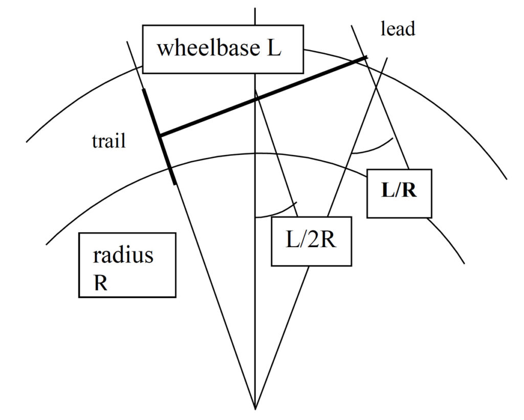
If a bogie were rigid, it would curve approximately as shown, with the trailing wheelset radial to the curve and almost at the so-called “equilibrium rolling line”, where the rolling radius difference between wheels compensates for the difference in radius between inner and outer rails. The leading wheelset has both an “angle of attack” to the direction of travel and curves outside the equilibrium rolling line.
Consequently for almost all conditions, tangential forces are very much higher at the leading wheelset: leading wheels cause more damage. Decreasing curve radius in general increases tangential curving force.
A bogie “steers” better i.e. with lower tangential forces, if the in-plane suspension is made more flexible: this allows the leading wheelset to become more radial and move towards the equilibrium rolling line. Applied traction counteracts this effect, and straightens the bogie out i.e. makes it curve more like a rigid bogie. Under high applied traction, wheels on the high rail are close to slipping even in gentle curves.
Increasing cant tends to move the trailing wheelset towards the inner rail, thereby allowing the leading wheelset to develop even higher “angle of attack”, greater tangential force and a greater difference in tangential force across a wheelset. Excessive cant exacerbates surface damage.
Conversely, under cant deficiency the trailing wheelset moves out to the high rail and the leading wheelset adopts a lower angle of attack. Tangential forces are very much more favourable. If movement towards the high rail gives more gauge face contact, lubrication should be provided to reduce wear.
For the leading wheelset the high rail wheel pushes the rail backwards and towards the inside of a curve for the full range of applied traction; the phase varies relatively little. This is consistent, for example, with the small (but significant) variation in direction of GCC cracks seen on the high rail. The direction of tangential force on the low rail is determined primarily by the angle of attack, which forces the rails to the inside of the curve (lateral force, corresponding to a phase of +90°). This is consistent with most damage seen on the low rail, particularly plastic flow. A longitudinal braking force is superposed on this for low applied traction, and a driving force for applied traction of T/N=0.28. For intermediate values of T/N, which are typical of metro vehicles with all wheels motored, there is a purely lateral force on the low rail.
