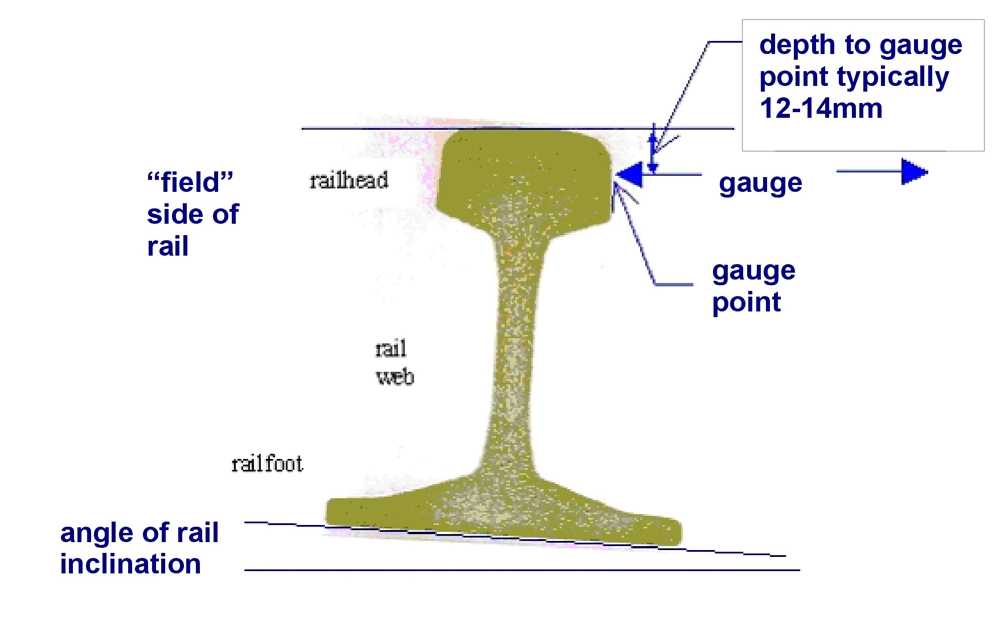
Rails are installed at a nominal angle of inclination, which is commonly in the range 1.43°-2.86° (1:40 to 1:20). This is usually equal to the angle of the wheel tread at the tread datum position so that a wheelset could ideally run with the datum position on each tread contacting the centre of each rail crown. Rails in switches and crossings and grooved rails for tram and light rail vehicles are often laid vertically.

Gauge is the distance between the two running rails. This is measured between the “gauge point” on the rails, which is at a distance of typically 12-14mm (depending on the network) below the reference line that is formed by a straight edge lying on the crown of both running rails in track.
The high rail is the outer rail in a curve and the low rail is the inner rail. The difference in height is the cant, which compensates partially for curving forces. The equilibrium cant required for a vehicle on standard gauge track (distance of 1.52m between rail centres) to travel through a curve of radius R (m) at speed v (km/h) is:
Cant excess or deficiency significantly influences curving behaviour of a vehicle, forces exerted on the rail and therefore rail damage. If the cant is less than the equilibrium value, vehicles curve with cant deficiency. If the cant is greater than this value vehicles curve with cant excess.

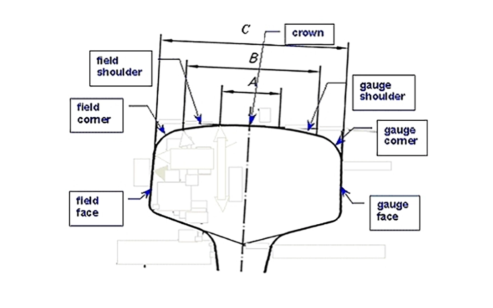
The area of the railhead on which wheels can run is considered to comprise several smaller areas, shown above, within which different types of damage can occur. The crown is essentially the area shown as A, while the shoulders (gauge towards the opposite rail, field facing the outside of the track) lie between A and B. The corners lie between B and C. The side of the rail is known as the face. Common rail sections (for example those defined in European and other standards) comprise a series of arcs, with a relatively large radius for the crown, a smaller radius for the shoulders and an even smaller radius for the corners. The European 60E1 profile comprises arcs of 300mm, 80mm and 13mm radius, while the 60E2 profile has arcs of 200mm, 70mm and 16mm.
In straight track, wheels should ideally run along the rail crown. Contact between wheels and the gauge face should occur only in severe curves. Contact occurs on the gauge shoulder in most curves, since this gives rise to a rolling radius difference between wheels on the same wheelset, thereby helping it to roll around the curve.